RC cars may be a hobby for some but knowing how to tweak the ESC to get the most out of your RC device is what distinguishes a true fanatic from a hobbyist. But even someone who is a professional RC driver may not know the nitty-gritty of its power system, like the electronic speed control or ESC. Don’t worry it isn’t your fault. It’s just the ESC manufacturers who don’t want to give you the inside scoop.

But what is an ESC?
Electronic speed control or just speed control is what differentiates a $100 RC toy from a professional RC racing vehicle. Basically, a speed control is what takes the signals from the receiver, decodes the signals and sends a power signal to your brushless motor. This is what helps in getting your RC vehicle moving. So, whether you are building your own RC car model or looking to make some changes in a pre-built model, having some information on the ESC might provide you with more insight to this mysterious box.
In this article, we will specifically highlight the information about ESC that manufacturers tend to hide from geeks like us.
BEC Voltage from ESC in RC cars
The BEC, or the battery eliminator circuit, is present on the ESC and it “eliminates” the need to use an external battery pack to supply power to the receiver and other servos onboard. The ESC has a circuit that utilizes the battery voltage of your vehicle and reduces it to the amount of voltage required for the receiver and servos. Simply, this would be a power source for an RC vehicle, just like the power supply found inside a PC or server room within an office. These power supplies convert the typical 120 volts to 5, 12, 24 volts. However, if the PC loads its power supply, it is unlikely that the voltage will sag significantly within this system.
The simplest way to understand this is by understanding the following scenario: A server room power supply for providing source power for an RC charger charging either a 6s pack or 2 6s packs at 10 amps each. No matter what the case, there is a negligible drop in the voltage going inside the RC charger.
However, this is not the case for an ESC. Why?
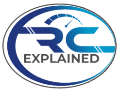
Manufactures don’t want you to know this but the BEC current as advertised by the manufacture of the ESC is not always accurate. When we tested speed controls at the mentioned continuous power, a 25% reduction in the voltage value was observed, however, this depends on the type of RC vehicle. Do be careful as this 25% drop can cause issues with receivers that we will cover here shortly.
Building your RC vehicle
Those who want to build their own RC vehicles by using an ESC must understand speed control’s BEC. That’s because modern-day radio devices have a minimum voltage level that needs a check and balance. If the voltage tends to fall below the minimum threshold, your vehicle might become unmanageable or even shut off. Following that, your RC vehicle’s receiver will restart and try to acquire signals from its transmitter to send them back to all systems onboard. This will take some time and even increase the chances of your RC vehicle crashing into something.
Key Takeaway
As long as the power onboard is stable, the radio system of your vehicle will be functional. We also recommend checking the maximum threshold voltage on your servos as well as your RC car’s receiver. Next, set the BEC voltage on your speed control at the same maximum threshold. This will allow the servos to produce maximum torque within their operational range, and operate at a higher functional speed. If the voltage from BEC begins to drop, the voltage at the receiver may be below its minimum threshold. If this does happen, signals being sent to the receiver will be disrupted.
To help prevent this from happening, the recommended voltage for operating most systems is 5.5 to 6 volt or more. This is because most radio system begin to suffer from voltage loss between 3.5 and 4.5V.
Maximum Continuous Current Rating on an ESC
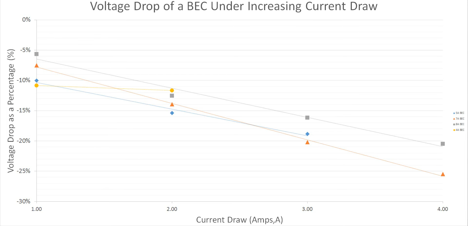
The maximum continuous current rating, mentioned on the labels of all speed control in boldface, is the maximum current the vehicle’s motor system can produce. All ESC manufacturers are mindful of mentioning this since it is a very important figure.
But what does it actually mean? Does it imply that an ESC with a 60-amp rating can sustain a continuous current of 60 amp?
Not necessarily.
This is because we are not sure if the ESC manufacturer has tested this rating based on their operating conditions. What are these operating conditions you might ask?
A certain amount of airflow could be one example. The airflow over the speed control will keep the ESC functional and stable to allow waste heat to pass. This is not always mentioned in the instruction manual of RC devices as it isn’t required for every speed control.
Another important figure for us is the amount of heat within the ESC. This will help us to determine what the actual continuous current is in our environment. Try to record the heat generated within the ESC. Measuring temperature is the easiest way to do this. If it exceeds the required amount, this will be the RC device’s new maximum limit.
Although a lot of RC drivers are running over the 60 amps limit, that is only recommended if you are fully aware of what you are doing and recording temperature changes within the ESC.
Key Takeaway
If you are not an expert, it is recommended that you run your RC car or airplane within the mentioned current rating or its maximum temperature. No matter which threshold is reached first, stick with that.
Partial Throttle of ESC
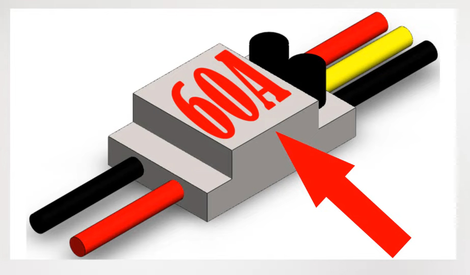
A lot of RC drivers out there might not know but operating your speed control at partial throttle is inefficient and can be detrimental for your device. The closer the speed control operates to just above the 0% threshold, the less efficient it is going to be. Beware, efficiency here implies the resultant mechanical output from the electrical input to the system.
From an experimental point of view, we have observed that the speed control is most efficient at 100% throttle, and at the 50% threshold or below, efficiency drops.
Key Takeaway
To utilize your RC vehicle’s full potential, and if your primary concern is efficiency, try to operate its speed control at 100% throttle. For most general RC applications this is obviously not practical. We don’t recommend using a pylon racer at 100% throttle and operate the device at 3000 miles/hour in a circle. Not all that practical indeed.
However, your RC airplane’s cruise speed must be at 100% if you wish to get maximum range for an FPV long distance build. This also points to the discussion towards PWM switching.
PWM Switching Rate within ESC
An RC vehicle can make use of partial throttle, by reducing the signals sent to the motor. If the RC device operates at 100% throttle, its motor will reach its maximum rotational speed, however, to reduce that speed, the ESC will introduce PWM switching.
But here’s the catch.
ESC manufacturers don’t want you to know that by increasing the PWM switching rate, your speed control and the motor would become more efficient.
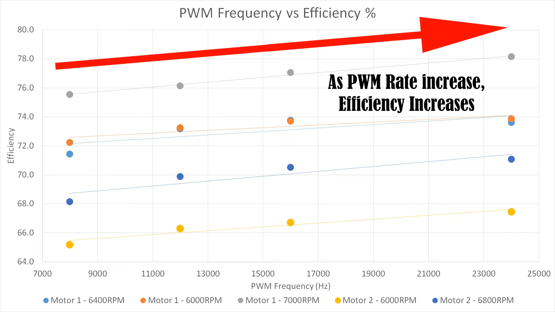
Why are they hiding this useful piece of information? ESC manufacturers don’t want you to know this because increasing the switching rate would burden the speed control. The speed control will introduce more heat in to the system, but the motor will become more efficient. The net result is efficiency gain as the motors gain is far more than the loss from the speed control.
Key Takeaway
Therefore, you want to make sure that you experiment with the PWM switching to attain maximum efficiency. However, be cautious about the temperature of the speed control.
Final words
Being an RC driver is about experimenting with speed control to get the most out of your RC device. However, take all precautionary steps to ensure proper operating temperature of your vehicle’s system.